Week 2
Mechanical:
Bumpers:
Put brackets on the outside bumper and predrilled the pilot holes in the wood of the bumpers. We taped the pool noodles together of to structure the bumpers. Re-checked the bumper measurement before attaching the pool noodles together and successfully taped the pool noodles for the 2nd bumper.
KOP Bot:
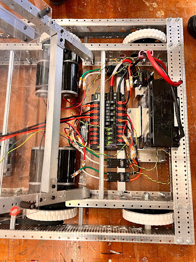
They installed the Lexan baseplate on the bottom of the bot in order for the electrical components. Added Wago splice connectors onto wires of motors and Talon motor controllers and mounted 4 Talons to the Lexan baseplate with VHB tape. Connected Talon to PDP using in splice connector, wire stripper, and flush cutter and attached Talon onto launcher frame. Connected the launcher CIM motors to Talon and connected CIM launcher motor Talons to PDP. As well as finished the CAN wiring.
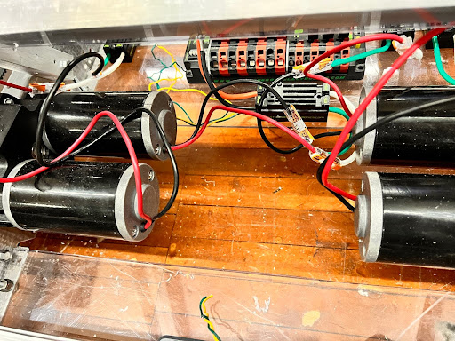
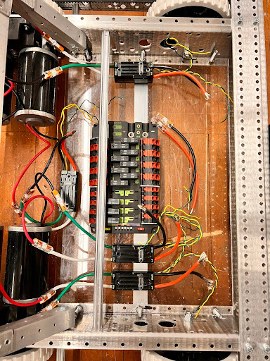
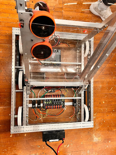
Then the team mounted the circuit breaker and plugged the battery into the circuit breaker. In order to organize the wires, we zip-tied the wires together which enhances the space within the robot. Connected 22 gauge wires to robo rio and connected the robo rio to the PDH. The team numbered the talons, mounted the radio, trapped the battery, and added signal lights to the robot.
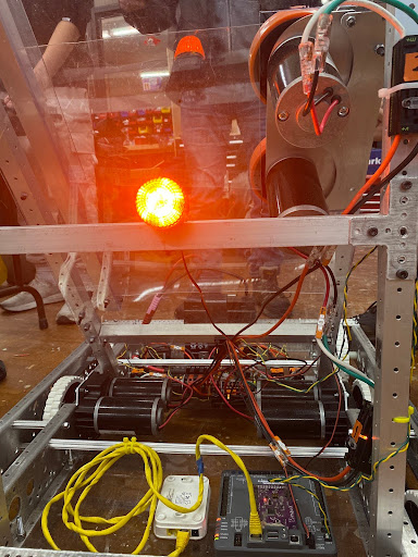
Debured the belly plate of the robot and updated the robo rio. The team then used the NASA method to solder CAN wires.
Intake:
Built the intake prototype and tested the intake with an impact drill. Attached the shaft using quarter 20 bolts and put a little material in the hole to lock it Polycord kept falling off so we attempted to use string. The string is not effective as there is no friction and is wearing out so rubber will have to be used.
String was used to fill in excess space between the bottom shaft and the hole because the hole was too large and since the bottom shaft was too short so were planning to use a churro spacer. We drilled the rest of the holes on the polycarbonate that connect the Lexan rollers with the shaft and we used screws and nuts to attach the polycarbonate. The broken polycarbonate pieces were 3D printed so attached all the polycarbonate pieces to the Lexan rollers. However, the slot for the nuts on one of the polycarbonate pieces is a bit too wide so the nut is actively spinning; we are unable to remove the screw or make it tighter.
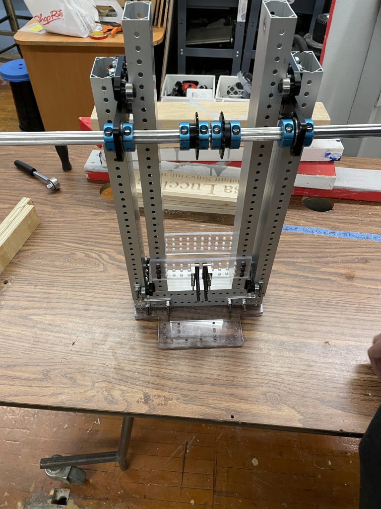
Elevator:
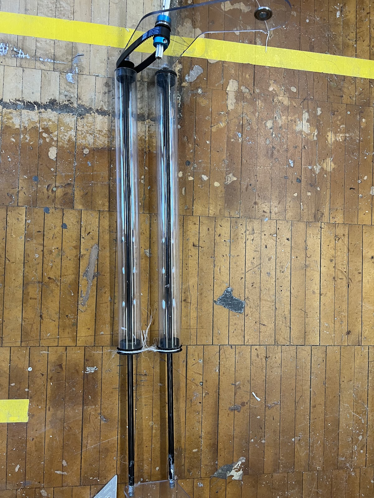
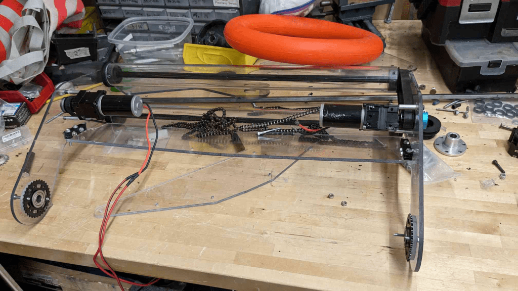
The elevator team was testing out the correct length of the chain with the turnbuckle on for the elevator while having the max planetary at the bottom. It took a couple of tries with the chain break in order to get the right tension on the chain when wrapped around the max planetary.
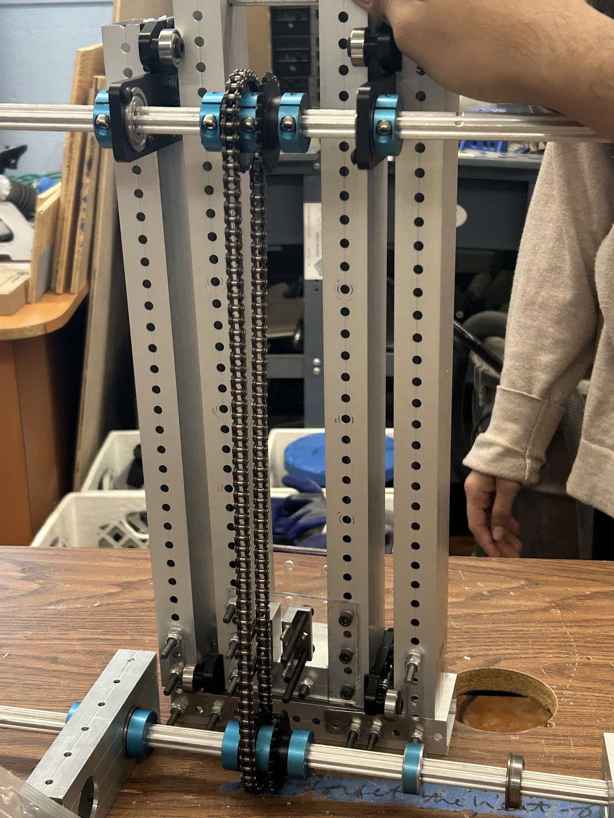
Removed the base 1×2 aluminum tube of the outer stage since it was not the correct spacing of the holes and it was bent. We cut a new 7-inch aluminum piece with pre-drilled holes all around the tubing in order to mount the elevator easier to the baseplate that was CNC’d out of Lexan with 1/4 20’s. The team corrected and found the right length of chain that we needed which was 31.5 inches excluding the turnbuckle. However, we found that the inner stage of the elevator would wiggle and shimmy inside the outer stage when it was supposed to be stationary. We found out the reason why and it was because the inner stage was not spaced out correctly so there was room for it to shimmy. In order to combat this, we CNC’d Lexan plates that connect the inner stage and hold it in place with the right width. We assembled the NEO mount for the elevator that was a 25:1 gear ratio on both sides. Used empty universal stage to connect NEO to gearboxes on the left side. We adjusted the shaft collars on the churros in order to correctly line up the outer stage with the correct spacing in order to reduce any more wiggling. We found a flaw though, the elvator was not mounted in the center of the robot and it was not spaced correctly. To fix this we would need to widen the elevator. We cut a 9 1/2 inch aluminum piece for the bottom of the outer stage and CNC’d a new Lexan plate for the inner stage to be correctly aligned that is 6 1/2 inches long.